2015 年全国大学生电子设计竞赛刚刚结束。我们组选择了 B 题:风力摆控制系统。题目要求如下:
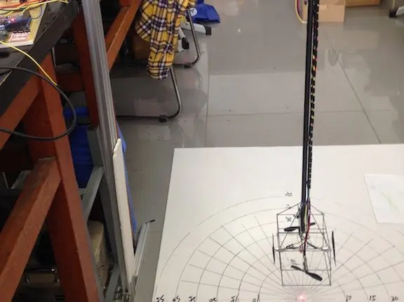
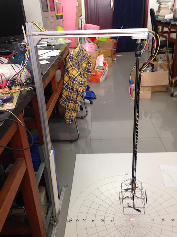
一长约 60cm~70cm 的细管上端用万向节固定在支架上,下方悬挂一组 (2~4 只) 直流风机,构成一风力摆,如图 1 所示。风力摆上安装一向下的激光笔,静止时,激光笔的下端距地面不超过 20cm。设计一测控系统,控制驱动各风机使风力摆按照一定规律运动,激光笔在地面画出要求的轨迹。
趁这段时间,整理一下我们组的方案。
总体方案
作品的机械结构由我的队友完成。支架使用铝型材制作,通过万向节与摆杆相连,底部是由细碳纤杆做成的立方体,四个电机固定在立方体的四个侧面上。
该题的电路比较简单,Arduno MEGA 2560 产生四路 PWM 波,通过 PMV31XN 驱动各个电机;MPU-6050 用于获取摆的运动状态。为了方便设置,作品上还安装了三个微动开关和一个 SSD1306 OLED 显示屏。
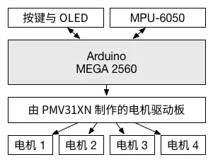
MPU-6050 固定在摆杆上,传感器 X, Y 轴的方向与两组电机轴的方向一致。(类似于四旋翼中的 "+" 模式。)
基本要求一:起摆
题目的要求如下:
从静止开始,15s 内控制风力摆做类似自由摆运动,使激光笔稳定地
在地面画出一条长度不短于 50cm 的直线段,其线性度偏差不大于 ±2.5cm,并且具有较好的重复性。
自由摆的摆动相当于左右方向的往复运动,在没有外力的情况下,由于阻力的影响,摆幅会逐渐降低。而在摆运动的过程中,不断给摆补充能量,就会使摆幅不断增大。
按照我们的方案,风力摆向左摆动时,给风力摆施加向左的力,向右运动时施加向右的力,风力摆就会越摆越高。从 MPU-6050 中读取的角速度正负,正好对应摆动的左右方向。
程序如下:
void app_mode1(void) {
    initMPU_NoDMP();        // 初始化 MPU-6050
    Serial.println("App mode1 initialized!");
    beep();

    for(;;) {
        getMotion6_NoDMP();  // 从 MPU-6050 读取角速度和加速度
        if(gx > 0) {         // 如果 X 轴的角速度大于 0
            motorOutput13(255);  // 电机 1 转动,给风力摆正方向的力
        } else {
            motorOutput13(-255); // 电机 3 转动,给风力摆反方向的力
        }

        delay(50);
    }
}
基本要求二:完成幅度可控的摆动
从静止开始,15s 内完成幅度可控的摆动。画出长度在 30~60cm 间可设置,长度偏差不大于 ±2.5cm 的直线段,并且具有较好的重复性。
将题目中的线段长度换算为风力摆需要达到的摆动幅度(角度)。在风力摆运动的过程中,通过 MPU-6050 实时获取目前的摆动幅度,通过 PID 算法控制电机转速,即可使风力摆逐渐达到要求的摆幅。
对于摆动幅度的获取,首先通过 MPU-6050 读取角速度,角速度为 0 时,说明风力摆已到达最高点。此时,可通过 MPU-6050 的 DMP 读取四元数,并换算为摆幅角度。
void app_mode2(void) {
    float theta_in, theta_out, theta_set, theta_last = 0;
    PID theta_pid(&theta_in, &theta_out, &theta_set, 5.0, 1.3, 2.0, DIRECT);
    int16_t gx_last = 0;
    bool a = 0;

    theta_pid.SetMode(AUTOMATIC);
    theta_pid.SetOutputLimits(-255, 255);
    theta_pid.SetSampleTime(1500);

    Serial.println("App mode2 initialized!");
    theta_set = interface_input_length();   // 输入长度

    if(theta_set <= 35) { theta_pid.SetTunings(1.0, 0.7, 1.0); }
    else if(theta_set <= 45) { theta_pid.SetTunings(8.0, 7.0, 2.0); }
    else { theta_pid.SetTunings(5.0, 7.0, 2.0); }  // 设置 PID 参数
    Serial.print("Length set: ");
    Serial.print(theta_set);
    Serial.print(". ");
    theta_set = atan((theta_set / 2) / 88.7);
    theta_set *= 180 /M_PI;    // 将长度换算为以角度为单位的摆动幅度
    Serial.print("Angle set: ");
    Serial.print(theta_set);
    Serial.print(". \n");

    initMPU();
    beep();

    for(;;) {
        if (gx == 0 || (gx > 0 && gx_last < 0) || (gx < 0 && gx_last > 0)) {
            // 角速度为 0,摆动到最高点,获取此时摆动幅度
            if(a == 0) {
                a = 1;
                theta_in = atan(sqrt(pow(tan(ypr[1]), 2.0) + pow(tan(ypr[2]), 2.0))) * 180.0 / M_PI;  // 将 pitch 和 roll 换算为摆动幅度
            } else {
                a = 0;
                theta_in += atan(sqrt(pow(tan(ypr[1]), 2.0) + pow(tan(ypr[2]), 2.0))) * 180.0 / M_PI;
                theta_in /= 2.0;      // 两次的摆动幅度(最大摆动角度)取平均值
                if(theta_in > 80) {
                    theta_in = theta_last;
                    theta_pid.Compute();  // 计算 PID
                } else {
                    theta_pid.Compute();
                }
                theta_last = theta_in;
            }
        }

        Serial.println(theta_in);
        Serial.println(", ");
        Serial.println(theta_out);

        if(abs(theta_out) < 2) { theta_out = 100; } // 保证在静止的时候依旧能摆起来
        if(gx > 0) {
            motorOutput13(theta_out);
        } else {
            motorOutput13(-theta_out);
        }

        gx_last = gx;

        while (!mpuInterrupt && fifoCount < packetSize) {}
        getYPR();           // 获取 yaw, roll, pitch
        getMotion6_NoDMP(); // 获取角速度和加速度
     }
}
基本要求三:按照指定方向摆动
可设定摆动方向,风力摆从静止开始,15s 内按照设置的方向(角度)摆动,画出不短于 20cm 的直线段。
根据力的合成与分解,控制两对电机的转速,即可做到按照指定方向摆动。其余部分与基础要求一类似。
void app_mode3(void) {
    uint16_t angle_input = 0;
    int16_t motor_val1, motor_val2;

    initMPU_NoDMP();
    Serial.println("App mode3 initialized!");
    Serial.println("Input radius:");
    angle_input = interface_input_angle();  //输入角度

    //if(angle_input == 120) { angle_input = 130; }  // 手动修正误差

    /* 计算两对电机的转速 */
    motor_val1 = 120 * sin(angle_input * M_PI / 180);
    motor_val2 = 120 * cos(angle_input * M_PI / 180);

    beep();

    for(;;) {
        getMotion6_NoDMP();

        if (gx > 0) {   // 以 90 度摆动时,只判断 gx 可能会出现问题。由于比赛时间限制,没有来得及修改。
            motorOutput13(motor_val1);
            motorOutput24(motor_val2);
        } else {
            motorOutput13(-motor_val1);
            motorOutput24(-motor_val2);
        }
    }
}
基本要求四:制动
将风力摆拉起一定角度 (30°~45°) 放开,5s 内使风力摆制动达到静止状态。
本要求刚好与基本要求一相反,在风力摆运动的过程中,给风力摆一个与运动方向相反的力,即可消耗其能量,使风力摆快速停下。这个力的大小,应该根据摆的运动速度实时调整,防止在摆在接近停止时来回振荡。
void app_mode4(void) {
    float kp_x = -0.1, kp_y = -0.1;
    int16_t output_x = 0, output_y = 0;
    initMPU_NoDMP();
    delay(400);
    Serial.println("App mode4 initialized!");

    beep();
    for(;;) {
        getMotion6_NoDMP();

        /* 计算两对电机的转速 */
        output_x = gx * kp_x;
        output_y = gy * kp_y; // kp_x 和 kp_y 均为负数,说明风机施加的力与运动方向相反

        //Serial.println(output_x);

        if(output_x < -255) { output_x = -255; }
        else if(output_x > 255 ) { output_x =  255; }
        if(output_y < -255) { output_y = -255; }
        else if(output_y > 255 ) { output_y =  255; }

        motorOutput13(output_x);
        motorOutput24(output_y);

        delay(4);
    }
}
发挥要求:画圆
(1) 以风力摆静止时激光笔的光点为圆心,驱动风力摆用激光笔在地面画圆,30s 内需重复 3 次;圆半径可在 15~35cm 范围内设置,激光笔画出的轨迹应落在指定半径 ±2.5cm 的圆环内;
(2) 在发挥部分 (1) 后继续作圆周运动,在距离风力摆 1~2m 距离内用一台 50~60W 台扇在水平方向吹向风力摆,台扇吹 5s 后停止,风力摆能够在 5s 内恢复发挥部分 (1) 规定的圆周运动,激光笔画出符合要求的轨迹;
圆锥摆相当于两个方向相互垂直的单摆的叠加,其相位差为 90 度。所以需要在基础要求二的基础上,对 X, Y 轴分别进行 PID 控制。同时需要提前测量好周期,控制好相位,否则无法画出正圆。
由于在完成本要求时,已经是比赛的最后一天,参数没调好,再加上程序应该还有更多优化的空间,在实验室调试时,算是勉强完成题目的要求。但在正式比赛的过程中,画出的圆有了较大的变形,再加上参数没调好,出现了振荡的现象,最终成绩不是太好。
void app_mode5(void) {
    const uint8_t delayTime = 120; // 电机转速更新周期,应根据摆的周期,结合实测结果进行微调,否则画出的圆会出现变形
    float currentAngle = 0.0;
    float i;

    unsigned long lastTime = 0, currentTime = 0;
    float theta_in,   theta_out,   theta_set,   theta_last   = 0;
    float theta_in_2, theta_out_2, theta_set_2, theta_last_2 = 0;
    PID theta_pid(  &theta_in, &theta_out, &theta_set, 6.0, 1.2, 5.1, DIRECT); // X 方向 PID
    PID theta_pid_2(&theta_in_2, &theta_out_2, &theta_set_2, 8.0, 1.5, 3.5, DIRECT);  // Y 方向 PID
    int16_t gx_last = 0, gy_last = 0;
    bool a = 0, a_2 = 0;

    theta_pid.SetMode(AUTOMATIC);
    theta_pid.SetOutputLimits(-255, 255);
    theta_pid.SetSampleTime(1500);
    theta_pid_2.SetMode(AUTOMATIC);
    theta_pid_2.SetOutputLimits(-255, 255);
    theta_pid_2.SetSampleTime(1500);

    Serial.println("App mode5 initialized!");
    theta_set = interface_input_radius() * 2.0 + 1.0; // 输入半径,换算为直径。1.0 为人工误差修正
    theta_set_2 = theta_set;

    initMPU();

    Serial.print("Length set: ");
    Serial.print(theta_set);
    Serial.print(". ");
    theta_set    = atan((theta_set   / 2) / 88.7);
    theta_set   *= 180 /M_PI;
    theta_set_2  = atan((theta_set_2 / 2) / 88.7);
    theta_set_2 *= 180 /M_PI; // 将直径换算为摆动角度
    Serial.print("Angle set: ");
    Serial.print(theta_set);
    Serial.print(". \n");

    beep();

    for(;;) {
        while (!mpuInterrupt && fifoCount < packetSize) {}
        getYPR();
        getMotion6_NoDMP();

        /* 在 X 方向进行 PID 控制 */
        if (gx == 0 || (gx > 0 && gx_last < 0) || (gx < 0 && gx_last > 0)) {
            if(a == 0) {
                a = 1;
                theta_in = atan(sqrt(pow(tan(ypr[1]), 2.0) + pow(tan(ypr[2]), 2.0))) * 180.0 / M_PI;
            } else {
                a = 0;
                theta_in += atan(sqrt(pow(tan(ypr[1]), 2.0) + pow(tan(ypr[2]), 2.0))) * 180.0 / M_PI;
                theta_in /= 2.0;
                if(theta_in > 80) {
                    theta_in = theta_last;
                    theta_pid.Compute();
                } else {
                    theta_pid.Compute();
                }
                theta_last = theta_in;
            }
        }

        /* 在 Y 方向进行 PID 控制 */
        if (gy == 0 || (gy > 0 && gy_last < 0) || (gy < 0 && gy_last > 0)) {
            if(a_2 == 0) {
                a_2 = 1;
                theta_in_2 = atan(sqrt(pow(tan(ypr[1]), 2.0) + pow(tan(ypr[2]), 2.0))) * 180.0 / M_PI;
            } else {
                a_2 = 0;
                theta_in_2 += atan(sqrt(pow(tan(ypr[1]), 2.0) + pow(tan(ypr[2]), 2.0))) * 180.0 / M_PI;
                theta_in_2 /= 2.0;
                if(theta_in_2 > 80) {
                    theta_in_2 = theta_last_2;
                    theta_pid_2.Compute();
                } else {
                    theta_pid_2.Compute();
                }
                theta_last_2 = theta_in_2;
            }
        }

        if(abs(theta_out) < 2) { theta_out = 60.0; }
        if(abs(theta_out_2) < 2) { theta_out_2 = 60.0; }

        /* 在指定的时间间隔更新电机转速 */
        currentTime = millis();
        i = (currentTime - lastTime) / delayTime;
        if(i > 0){
            currentAngle += 30.0 * i;
            if(currentAngle >= 360) { currentAngle = 0.0; }
            motorOutput13(theta_out   * sin(currentAngle * M_PI / 180.0));
            motorOutput24(theta_out_2 * cos(currentAngle * M_PI / 180.0));
            lastTime = currentTime;
        }

        gx_last = gx;
        gy_last = gy;
    }
}

您好,我是一名学生,目前正在学习风力摆,目前在画直线这一步卡住了,请问一下您的源代码可以分享一下吗?我想学习学习,O(∩_∩)O谢谢!
其实文章中的已经是最关键的代码了。完整代码在这里:https://github.com/blanboom/Wind-Pendulum
请问你们有没有用74hc595扩展io口
你们的代码好像没有用74hc5959扩展io口,,这是怎么做到的呢
控制四个电机,用四个 IO 口就可以了吧
那还有按键 液晶屏的接口呢
液晶屏用 I2C 总线,占两个 IO 口;按键占一到三个 IO 口,也够用了。还不够的话,选个 IO 口更多的单片机就可以,没必要用别的芯片增加复杂度。
您好,我下载了您发布的源码,可是imu.cpp中包含的库是缺失的,编译报错信息为 I2Cdev.h: No such file or directory,我看到github上有一个路径为 / EDC2015 / [Documents] /四旋翼资料整理/ Arduino-Quadcopter ”可是下载到的资料中没有。能否上传一下或者告诉我哪儿能下载到这些库文件,感激不尽
可以在这里下载到:
https://github.com/jrowberg/i2cdevlib
在解决了一些其他小问题后,它被成功编译了,谢谢!
不过我看到您的代码中loop中是空的,只在setup中有case去选择题目,是每次更改题目都需要重启arduino吗?
对,Arduino 上有复位键,重启还是挺方便的😂
为什么我的选了模式之后就不能对长度和角度进行选择了呀
相关数值是写死在程序里面的,需要手动修改
我改了很多 但都没用
大概要改哪块地方 头都快炸了
可以看下 app_mode2() 里面的 theta_set